After passing the VCP-VCF exam and receiving a one-year VCF license, I wanted to deploy the full VCF stack in this nested environment. However, physical limitations… primarily available RAM on my Dell PowerEdge R630 forced some compromises. Instead of a fully automated, multi-domain, HA-capable deployment, I ended up with a single VCF instance, without a separate workload domain and without VCF Automation.
This post walks through how I designed and deployed that constrained VCF lab, what broke along the way, and the exact settings and workarounds that got it running.
Before nesting anything, I started with the bare-metal layer on the Dell PowerEdge R630.
| Component | Configuration |
|---|---|
| Server | Dell PowerEdge R630 |
| CPUs | Intel(R) Xeon(R) CPU E5-2650L v3 (12 cores) x2 |
| Memory | 192 GB DDR4 ECC LRDIMM |
| Storage | 2x HDD 1.2TB / 2x 120GB SSD / 2x 500GB SSD |
| Network | Intel(R) GbE 4P I350-t rNDC |
| Hypervisor | 7.0 Update 3 Build-24585291 |
| Management | Dell iDRAC 8 |
| Switch | TP-Link TL-SG108E |
| Virtual router | VyOS VM |
| Infrastructure subnet | 192.168.100.0/24 |
| Nested lab network | VLAN 4095 trunk |
| Nested ESXi management subnet | 172.20.100.0/24 |
| Nested ESXi hosts | lab-esx01, lab-esx02, lab-esx03 |
| VCF version | VCF 9.0.2.0.25151285 |
ESXi install and basic config
I installed ESXi 7 directly on the physical server and kept this layer intentionally simple. No fancy storage policies, no distributed switching, just a clean hypervisor to host the nested lab.
Installation was straightforward:
- Mounted the ESXi 7 ISO through iDRAC.
- Installed ESXi on two small SSDs (120GB) configured in RAID1.
At this stage, the physical ESXi host itself had minimal configuration. All the complexity was meant to live in the nested layer.
Storage layout: HDD vs SSD
For storage, I split the local disks into two logical roles.
HDDs – general lab storage
- 2 × ~1.2 TB HDDs in RAID1.
- Used mainly for:
- VCF installer VM.
lab-dnsandlab-web01(offline depot, internal services).lab-rtr01(VyOS virtual router).- ISOs, templates, and miscellaneous lab files.
This datastore was my “general purpose” lab storage and stayed on RAID1 for simplicity and some redundancy.
SSDs – VCF-focused storage (and a mistake)
- 2 × 500 GB SSDs.
- Initially configured as RAID1, based on William Lam’s minimum requirements: for a thin-provisioned VCF deployment you need roughly 300 GB, so I assumed 2 × 500 GB in RAID1 would be more than enough.
That assumption turned out to be wrong.
During the VCF deployment, I ran out of space and the deployment failed. The SSD datastore filled up faster than expected once all VCF components and nested VMs were in place. (and maybe some snapshots that quickly filled in lol)
To recover:
- I deleted the three nested VMs that were consuming most of the space.
- Broke the existing RAID1 on the SSDs.
- Reconfigured them as RAID0 via iDRAC to maximize usable capacity (at the cost of redundancy).
- Recreated the datastores and redeployed the nested VMs.
This gave me enough room to continue, but it also highlighted that my initial capacity planning was too optimistic for a full VCF stack, even in a minimal nested design.
Design intent
The goal was to create a small but realistic vSphere cluster capable of:
- Running vCenter Server and VCF components.
- Supporting vSAN (including ESA) for shared storage.
- Providing VLAN-backed networks for isolated lab segments.
Everything had to fit within the physical RAM and CPU limits of the R630, while still being “realistic enough” to behave like a proper VCF environment.
Nested ESXi VM specification
For each nested ESXi host, I used the following baseline configuration:
- Guest OS type: VMware ESXi 9.0.2
- vCPU: 16 vCPU per nested host
- RAM: 64 GB per nested host
- Boot disk: 32 GB (standard ESXi boot device)
- Additional disks:
- 1 × 400 GB disk attached via an NVMe controller
- This was intentional: I wanted to test vSAN ESA
- Network adapters:
- 4 × vNICs per nested ESXi VM
- Adapter type: VMXNET3 where appropriate
This gave me a reasonably sized nested host for running the VCF components.
Virtualization and security settings
Because these are nested hypervisors, a few extra CPU and network options had to be enabled:
- Expose hardware-assisted virtualization to the guest OS: Enabled
(required for nested ESXi to run its own VMs) - Promiscuous mode: Accept
- Forged transmits: Accept
- MAC address changes: Accept
These settings were applied on the port groups / vSwitches that the nested ESXi VMs connect to. Without them, nested networking (especially with multiple vNICs, vSAN traffic, and VLANs) either fails or behaves unpredictably.
Network design
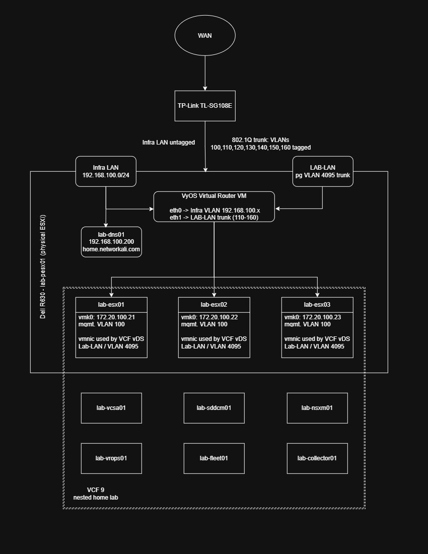
The network was designed to keep the nested VCF environment isolated from the physical home network while still allowing controlled access to external services. The design uses an infrastructure LAN for management and services, together with a VLAN-backed lab network for the nested ESXi hosts and VCF workload traffic.
The physical Dell PowerEdge R630 runs ESXi and hosts the complete nested environment. The physical ESXi management interface is connected to the infrastructure LAN, while the nested ESXi hosts use a VLAN trunk to carry the lab networks required by VCF.
High-level topology
WAN
 │
TP-Link TL-SG108E
 ├── Infrastructure LAN — untagged
 └── VLAN trunk — VLANs 100, 110, 120, 130, 140, 150, 160
      │
   LAB-LAN
      │
   VyOS virtual router
      │
   Nested ESXi hosts and VCF appliances
The TP-Link switch provides the physical connection between the home network and the lab. The physical ESXi host receives the required traffic through the switch, while VyOS provides routing between the infrastructure network and the isolated lab VLANs.
Infrastructure LAN
The infrastructure LAN uses the 192.168.100.0/24 subnet. This network is connected to the physical ESXi host and contains the services needed to support the lab.
The main infrastructure service shown in the design is:
| System | IP address | Purpose |
|---|---|---|
lab-dns01 | 192.168.100.200 | DNS and internal name resolution |
The infrastructure network is untagged from the perspective of the relevant physical connection. This made the initial physical ESXi deployment simpler and allowed the host and supporting services to communicate without requiring VLAN configuration at the bare-metal stage.
The DNS server was especially important because VCF and vSphere deployments depend heavily on reliable forward and reverse name resolution. I therefore kept DNS outside the nested VCF stack so that it would remain available while deploying or troubleshooting the nested environment.
VLAN-backed lab network
The lab network uses the LAB-LAN segment and carries multiple tagged VLANs over an 802.1Q trunk. The VLANs shown in the HLD are:
| VLAN | Intended role |
|---|---|
| 100 | ESXi management, vCenter, SDDC Manager, NSX Manager, DNS/NTP reachability |
| 110 | vMotion VMkernel traffic |
| 120 | vSAN VMkernel traffic |
| 130 | NSX Host TEP / overlay transport |
| 140 | NSX Edge TEP / Edge overlay transport |
| 150 | Edge uplink / north-south test connectivity |
| 160 | Optional workload/test VMs |
The trunk between the TP-Link switch and the lab environment carries VLANs 100, 110, 120, 130, 140, 150, and 160 as tagged traffic. This allows the nested environment to use separate logical networks without requiring separate physical interfaces for every segment.
VyOS virtual router
Using a VyOS virtual router was not only a design preference it became a constraint because I could not create the required static routes on the ISP router with the access available to me.
The VCF lab used isolated networks behind the LAB-LAN trunk, while supporting services such as DNS, the offline depot, and the physical ESXi host existed on the infrastructure network. Without routing between those networks, the VCF Installer and nested components could not consistently reach the services required during deployment.
VyOS gave me control over the parts of the network that mattered for the lab:
The flexibility to add or change lab VLANs without depending on ISP-router features.
Routing between the infrastructure LAN and the isolated lab VLANs.
Persistent static routes that survived reboots.
A controlled gateway for nested ESXi hosts and VCF appliances.
A clear network boundary between the home network and the disposable lab environment.
The router has two primary interfaces:
eth0connected to the infrastructure LAN, using the192.168.100.xnetwork.eth1connected to the LAB-LAN trunk, carrying the lab VLANs.
The VyOS VM acts as the boundary between the home infrastructure and the isolated nested VCF environment. It provides the routing and traffic control required for the lab while avoiding direct exposure of the nested networks to the wider physical network.
This also makes the environment easier to rebuild. The nested ESXi hosts, VCF appliances, and disposable workloads can be redeployed without redesigning the physical network every time. As long as the infrastructure LAN, trunk, VLANs, and VyOS configuration remain available, the nested lab can be recreated consistently.
Physical ESXi networking
The physical R630 runs ESXi 7 and provides the virtualization layer for the entire environment. At this stage, the physical networking was intentionally kept simple:
- The physical ESXi management network used the infrastructure LAN.
- The virtual machines requiring access to the lab networks were connected to the LAB-LAN trunk.
- VLAN tags were carried through the physical switch and virtual switching configuration to the nested environment.
- VyOS handled routing between the infrastructure and lab networks.
The physical ESXi host did not need to understand every individual lab network as a routed network. Its primary responsibility was to pass the required VLAN traffic to the appropriate virtual machines and nested ESXi hosts.
Nested ESXi management
The three nested ESXi hosts are:
| Host | Management network | Address |
|---|---|---|
lab-esx01 | VLAN 100 | 172.20.100.21 |
lab-esx02 | VLAN 100 | 172.20.100.22 |
lab-esx03 | VLAN 100 | 172.20.100.23 |
All three nested hosts use VLAN 100 for management. This keeps ESXi management traffic separate from the other VCF and workload networks.
The nested hosts are connected to the VCF virtual distributed switch. The distributed switch is used to provide the VLAN-backed connectivity required by the VCF appliances and workloads. At the physical ESXi layer, the relevant port group carries the lab traffic as a trunk so that the nested ESXi hosts can process the VLANs themselves.
VCF appliances and workloads
The nested VCF environment contains the following primary systems:
lab-vcsa01lab-sddcm01lab-nsxm01lab-vrops01lab-fleet01lab-collector01
These virtual machines are hosted on the nested ESXi cluster and use the VLAN-backed networks presented through the VCF distributed switch.
The design separates the physical infrastructure services from the nested VCF management stack:
Infrastructure LAN
 ├── Physical ESXi management
 ├── lab-dns01
 └── VyOS infrastructure-side interface

Lab VLANs
 ├── Nested ESXi management
 ├── VCF management traffic
 ├── NSX and VCF services
 └── Disposable workloads and test networks
This separation was useful during deployment because the DNS service and routing layer remained available independently of the VCF appliances being installed.
Nested networking requirements
Because ESXi is running inside virtual machines, the outer ESXi networking configuration must allow the nested hosts to behave like hypervisors. The relevant port groups therefore require:
- Promiscuous mode: Accept.
- Forged transmits: Accept.
- MAC address changes: Accept.
- VLAN trunking for the required lab VLANs.
- VMXNET3 adapters where supported.
- Hardware-assisted virtualization exposed to the nested ESXi guests.
Problems I hit and fixes
This was not a one-click VCF deployment. Most of the issues were not caused by a single major failure, but by small dependencies that became important only once the deployment started: memory compatibility, storage capacity, offline-depot structure, routing, DNS, and nested vSAN requirements.
The following table captures the issues that had the biggest impact on the build and the lessons I would apply before attempting the next deployment.
| Symptom / issue | Likely cause | Fix / lesson learned |
|---|---|---|
| RAM upgrade did not work as expected | I initially focused on capacity “32 GB DDR4 ECC” rather than the exact DIMM technology. The server’s existing memory and the upgrade modules were not compatible because of the RDIMM versus LRDIMM difference. | Verify the exact DIMM type already installed in the server before buying anything. Check the Dell R630 memory population guide, BIOS inventory, speed, rank, and population rules. Enterprise RAM is not interchangeable simply because the connector, speed, and capacity appear similar. |
| VCF deployment failed because the SSD datastore ran out of space | I initially used two 500 GB SSDs in RAID1. I assumed roughly 300 GB of usable storage would be enough. In practice, the nested ESXi hosts, VCF appliances, vSAN ESA disks, deployment activity, snapshots, and retries consumed more space than expected. | Capacity planning needs headroom, especially in a nested VCF lab. I deleted the three nested ESXi VMs, destroyed the SSD RAID1 virtual disk, and recreated it as RAID0 through iDRAC to gain the full usable capacity. This removed redundancy, but it was acceptable for a non-production learning lab. |
| Offline depot did not work correctly at first | Downloading the VCF binaries alone was not enough. The VCF Installer expects the correct offline-depot metadata and folder structure in addition to the software files. | I used William Lam’s offline-depot layout as the reference for organizing the metadata and VCF binaries. The metadata archive provides the expected directory structure, making it much easier to place each downloaded component in the correct location. |
| The offline depot required HTTPS, adding unnecessary complexity | My offline depot was an internal lab service, but the VCF Installer expects HTTPS by default. Setting up certificates for a temporary internal repository would have added extra work and another possible failure point. | I configured the VCF Installer to allow HTTP for the local offline depot and hosted it through lab-web01 on port 80. This was acceptable because the depot was reachable only within the isolated lab environment. The relevant setting was lcm.depot.adapter.httpsEnabled=false in /opt/vmware/vcf/lcm/lcm-app/conf/application-prod.properties, followed by an LCM service restart. See William Lam’s HTTP offline-depot guidance. |
| Nested VCF components could not consistently reach all required networks | My ISP router and the access available to me did not allow me to create the static routes needed between the home infrastructure network and the isolated lab networks. | I created persistent routes where I had control: on the VyOS router VM, on the VCF Installer, and on my workstation. This allowed required management, DNS, depot, and deployment traffic to reach the correct lab networks. |
| Routing changes disappeared after reboot or redeployment | Temporary route commands can solve a connectivity problem during testing, but they do not necessarily survive a restart. This becomes especially painful in a lab where the installer or router may be redeployed several times. | Make routes persistent from the beginning. On VyOS, save the active configuration after adding static routes. On the VCF Installer and administrative workstation, document the required routes and ensure they are configured persistently rather than relying only on temporary commands. |
| vSAN ESA disk was not eligible for claim | The nested ESXi hosts were configured with NVMe-backed disks so that I could test vSAN ESA, but the VCF validation or installer logic did not initially accept the virtual NVMe device as eligible. | I modified the VCF Installer configuration to allow the disk claim. echo "vsan.esa.sddc.managed.disk.claim=true" >> /etc/vmware/vcf/domainmanager/application-prod.properties, followed by a systemctl restart domainmanager. |
| Deployment failed after several attempts and became difficult to troubleshoot | After repeated failures, the installer and partially deployed components no longer represented a clean starting point. Retrying from a partially configured state made the next failure more difficult to isolate. | I redeployed the VCF Installer instead of continuing to patch an uncertain state. This cost time, but it restored a known-good starting point. In a home lab, rebuilding is often faster and more reliable than trying to recover every partial deployment artifact. |
| Nested ESXi networking did not behave as expected | Nested ESXi hosts generate MAC addresses and forward traffic for their own virtual machines. Default outer port-group security settings can block this behavior. | Enable promiscuous mode, forged transmits, and MAC address changes on the isolated port group used by the nested ESXi hosts. This allows the outer ESXi host to pass traffic from the nested hosts and their workloads correctly. |
The finished lab is less important than the process of getting there. A nested environment forces you to understand how physical hardware, firmware, hypervisor settings, virtual networking, DNS, storage, and resource allocation all depend on one another.
Because this is a low-budget home lab, it is not intended to be a perfect replica of a production VCF environment. It is a practical starting point: enough hardware and enough complexity to learn the fundamentals, validate ideas, and understand how the components fit together.
More importantly, it gives me a foundation to build on. Each limitation whether RAM, storage capacity, routing, or automation has become a clear target for the next upgrade or redesign. Rather than seeing those constraints as blockers, I see them as fuel to keep improving the lab, expanding its capabilities, and moving closer to a fully automated VCF environment with workload domains and VKS testing.